Table Of Content
Table Of Content
The short answer is yes: a properly designed M12 X-coded connectivity system can support 10 Gigabit Ethernet, including 10GBASE-T over Category 6A-class cabling.
But that answer is incomplete.
In professional AV, broadcast, industrial media, transportation, stadium, digital signage, machine vision, and harsh-environment AV-over-IP systems, the real engineering question is not simply whether an M12 X-coded connector has “10Gbps” written on a datasheet. The real question is whether the complete channel – connector, cable, terminations, shielding, routing, installation, environmental exposure, and active Ethernet interfaces – can preserve the signal integrity required by 10GBASE-T under actual operating conditions.
That distinction matters because 10 Gigabit Ethernet over copper is unforgiving. At 10Gbps, small discontinuities that are almost irrelevant at 100Mbps or even 1Gbps can become meaningful contributors to return loss, insertion loss, near-end crosstalk, alien crosstalk, common-mode conversion, and bit error performance.
For Pro AV system designers, integrators, OEM engineers, and product managers, M12 X-Code should therefore be understood not as “a rugged RJ45 replacement,” but as a high-frequency balanced interconnect architecture engineered for environments where a conventional office-style connector may be mechanically or environmentally inadequate.
Why M12 X-Code Can Support 10GbE
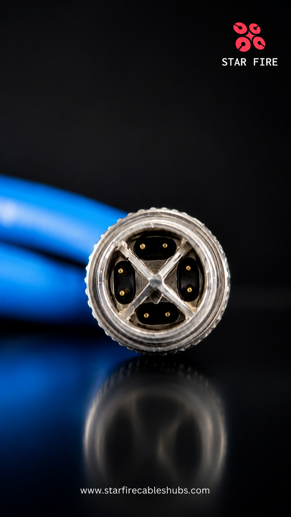
M12 X-Code is an 8-position circular connector arrangement designed for high-speed Ethernet applications. Its geometry supports four balanced differential pairs, which is exactly what 1000BASE-T and 10GBASE-T require.
The most important feature is not the pin count. It is the internal pair separation and shielding architecture.
At 10Gbps, four twisted pairs transmit simultaneously in both directions. The channel therefore has to control coupling between pairs while maintaining a nominal 100-ohm balanced impedance. M12 X-Code connectors use a cross-shaped internal separation structure that divides the eight contacts into four pair groups. This physical separation reduces pair-to-pair coupling and helps preserve the electrical behavior expected from a Category 6A-class channel.
IEC 61076-2-109 defines M12 connectors for data transmission frequencies up to 500MHz. Commercial M12 X-coded assemblies from major connector manufacturers are commonly specified for Category 6A and 10Gbps Ethernet, confirming that the interface is intended for 10G-class copper networking when implemented correctly.
This is why X-Code is fundamentally different from older M12 Ethernet codings.
M12 X-Code vs. D-Code: The Difference Is Electrical Architecture
M12 D-coded connectors are widely associated with Industrial Ethernet at 100Mbps and, in some implementations, 1Gbps. They use four contacts and two differential pairs.
M12 X-Code uses eight contacts and four differential pairs, with more aggressive separation and shielding between the pairs. That architecture is much better aligned with the electrical requirements of 10GBASE-T.
For a Pro AV engineer, the practical implication is simple:
- D-Code is appropriate for lower-speed Ethernet applications where two-pair connectivity is sufficient.
- X-Code is the preferred M12 coding when the design target is four-pair Gigabit Ethernet or 10 Gigabit Ethernet with Category 6A-class performance.
However, choosing X-Code does not automatically guarantee Category 6A channel performance. The connector is only one discontinuity within the total link.
10GBASE-T Is a Channel Problem, Not a Connector Problem
10GBASE-T, standardized by IEEE 802.3an, transmits 10Gbps over four copper pairs. The PHY uses sophisticated echo cancellation, equalization, crosstalk cancellation, coding, and digital signal processing. This makes the system remarkably robust – but it does not eliminate the laws of high-frequency transmission.
A real 10GbE channel still has to manage several electrical parameters.
Insertion Loss
Insertion loss measures how much signal energy is lost as the signal travels through the channel. Cable length, conductor size, dielectric material, frequency, temperature, connector transitions, and flex history can all influence it.
In a 10GbE Pro AV installation, excessive insertion loss reduces signal-to-noise margin. This may not always cause an immediate link failure. Instead, it can show up as intermittent packet errors, link renegotiation, reduced stability at elevated temperature, or failures that appear only when the cable is routed through a high-EMI environment.
Return Loss
Return loss is strongly influenced by impedance discontinuities. Every change in geometry – untwisting a pair too far, changing conductor spacing, poor shield termination, an inconsistent connector transition, or excessive deformation near the backshell – can create reflections.
At lower data rates, the PHY may tolerate a surprising amount of imperfection. At 10Gbps, the margin becomes much smaller.
NEXT and PSNEXT
Near-end crosstalk describes unwanted coupling from one pair into another near the transmitting end. Power-sum NEXT evaluates the combined impact of multiple disturbing pairs.
M12 X-Code's internal pair segregation is specifically valuable here. The cross-shaped geometry helps keep pair groups physically separated through the connector transition, reducing one of the common causes of high-frequency crosstalk.
Alien Crosstalk
Alien crosstalk comes from neighboring cables rather than other pairs inside the same cable. This is especially important in dense cable bundles, equipment racks, stage boxes, mobile production systems, LED processing cabinets, and AV-over-IP switch enclosures.
A single cable may pass a bench test but behave differently when tightly bundled beside multiple active 10G links. Cable construction, overall shielding, grounding strategy, bundle density, and thermal conditions can therefore matter as much as the connector itself.
Common-Mode Conversion
Balanced Ethernet relies on the differential relationship between two conductors in each pair. Mechanical asymmetry or electrical imbalance can convert differential energy into common-mode energy. That can increase emissions, reduce immunity, and make the link more vulnerable in electrically noisy environments.
For Pro AV systems installed near LED power supplies, motors, variable-frequency drives, lighting dimmers, high-current distribution, broadcast trucks, or industrial machinery, this is not a theoretical concern.
Why Pro AV Should Care About M12 X-Code
Most traditional AV installations use RJ45 because it is compact, familiar, inexpensive, and supported by almost every network device.
But modern Pro AV is increasingly deployed outside traditional office environments.
Consider these examples:
- Outdoor LED walls and digital signage
- Stadium and arena AV networks
- Theme parks and immersive attractions
- Broadcast and OB van systems
- Transportation terminals and rail platforms
- Factory-floor visualization and control rooms
- Industrial cameras used for machine vision and production monitoring
- Smart classrooms or training spaces integrated into laboratories and manufacturing environments
- Marine, mobile, and vibration-prone installations
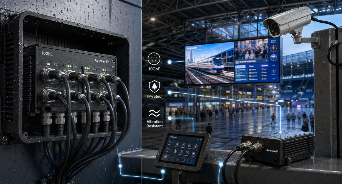
- AV-over-IP endpoints exposed to dust, moisture, shock, repeated movement, or washdown conditions
In these environments, the weak point may not be bandwidth. It may be connector retention, ingress protection, vibration resistance, shielding continuity, or the ability to maintain stable electrical performance after repeated mechanical stress.
This is where M12 X-Code becomes strategically relevant to Pro AV.
It combines high-speed Ethernet capability with a circular threaded interface that can be engineered for IP-rated, vibration-resistant, industrial connectivity.
“IP67” Does Not Mean “10GbE Will Always Work”
One of the most common specification mistakes is to combine environmental and electrical ratings as if they were the same thing.
They are not.
IP67 describes ingress protection under defined conditions. It does not prove Category 6A performance. Likewise, a connector advertised for 10Gbps does not automatically prove the entire cable assembly will maintain IP67 after repeated use, chemical exposure, extreme temperature cycling, or incorrect mating torque.
A high-quality M12 X-coded assembly for Pro AV should therefore be evaluated across at least four layers:
Electrical performance
Mechanical performance
Environmental performance
Manufacturing consistency
An assembly that is strong in only one of these areas can still fail in the field.
The Cable Matters as Much as the Connector
To achieve 10GbE performance, the cable construction must support the required bandwidth and noise margin.
Important variables include:
Conductor Gauge
Smaller conductors reduce cable diameter and improve flexibility, but they also increase DC resistance and insertion loss. The tradeoff becomes more important over longer distances and at elevated temperature.
Pair Twist Consistency
Each twisted pair has a controlled twist lay. Excessive untwist during termination can degrade crosstalk performance and impedance balance. For high-speed assemblies, the transition from twisted cable to connector contacts must be tightly controlled.
Shielding
Foil shielding, braid coverage, pair shielding, overall shielding, and 360-degree connector shield termination all affect EMC performance.
In a high-EMI Pro AV or industrial environment, simply having “shielded cable” is not enough. The continuity and geometry of the shield through the connector transition can determine whether the assembly actually provides the expected protection.
Jacket Material
PVC may be acceptable for static indoor installations. PUR or other industrial jacket materials may be preferable where abrasion resistance, oil resistance, drag-chain movement, cold flexibility, or repeated flexing are required.
A cable can be electrically capable of 10GbE while being mechanically unsuitable for the application. Conversely, a very rugged cable can still fail 10GbE electrical requirements if pair geometry is poorly controlled.
Length: Do Not Treat 100 Meters as a Universal Promise
Engineers often associate Category 6A and 10GBASE-T with a 100-meter structured cabling channel. That is a useful reference point, but it should not be blindly transferred into every rugged M12 cable assembly design.
The practical maximum length of a specific M12 X-coded link depends on the entire channel architecture:
- Cable insertion loss
- Conductor gauge
- Number of connector transitions
- M12-to-M12 versus M12-to-RJ45 transitions
- Patch cords and couplers
- Operating temperature
- Bundle size
- Flex requirements
- EMC environment
- PHY implementation
- Required engineering margin
A short M12 X-coded assembly used between a 10GbE industrial camera and a local switch is a very different engineering problem from a long building backbone.
For Pro AV, this leads to an important design principle: use copper where copper is electrically and mechanically efficient, and use fiber where distance, isolation, EMI immunity, or bandwidth margin justify it.
M12 X-Code should not be used to force copper into applications where fiber would produce a more robust system architecture.
M12 X-Code in 10GbE AV-over-IP
10GbE AV-over-IP is becoming relevant where systems require high aggregate throughput, visually lossless or lightly compressed video, high-resolution image transport, multi-stream production workflows, or low-latency media distribution.
In a conventional enterprise AV network, RJ45 and SFP/SFP+ interfaces dominate. In rugged Pro AV, however, the physical layer may need to survive environments that standard IT connectors were never designed for.
M12 X-Code can be useful in the edge segment of such systems:
Camera or Sensor to Rugged Switch
Industrial cameras, machine-vision systems, broadcast capture devices, and specialized imaging equipment may require high bandwidth close to machinery or outdoor equipment.
Rugged Switch to Local AV Node
A 10GbE M12 interface can support short, mechanically secure copper links between industrial switches and AV processing equipment.
Mobile and Temporary Systems
Repeated setup and teardown can expose connectors to mechanical stress. Threaded M12 interfaces can offer a more secure connection than friction-latch interfaces when properly specified.
Outdoor and Semi-Outdoor AV
For stadium displays, transportation systems, smart-city signage, and outdoor event infrastructure, an IP-rated M12 system can help reduce the risk of contamination and accidental disconnection.
The Hidden Risk: M12-to-RJ45 Hybrid Channels
Many real systems do not use M12 from end to end. A common configuration is M12 X-Code at the rugged device and RJ45 at the switch, media server, or control system.
This is electrically practical, and commercial Category 6A M12-to-RJ45 assemblies are widely available. But the transition should be treated as an engineered channel, not as a simple adapter.
Every transition can add:
- Impedance discontinuity
- Return loss
- Crosstalk
- Shield bonding variation
- Mechanical strain
The assembly should therefore be qualified as a complete high-speed cable, not built by combining a generic “Cat6A cable” with two connectors that are individually rated for 10Gbps.
At 10G, components do not automatically add up to a compliant system.
Shielding and Grounding: More Is Not Always Better
Pro AV professionals often assume that stronger shielding always improves performance. In practice, shielding only works as part of a controlled EMC design.
A high-quality M12 X-coded cable may include foil, braid, pair shielding, and a conductive connector shell. But the effectiveness of that shielding depends on how the shield is terminated at both ends and how chassis ground is handled in the system.
Poor bonding can create unexpected common-mode paths. In some systems, ground potential differences can also complicate the design.
For difficult environments, the correct question is not “Is the cable shielded?” It is:
“How is the shield terminated, and how does that termination interact with chassis ground, equipment bonding, and the system's EMC architecture?”
That is a much more useful engineering question.
Flexing, Vibration, and Installation Can Change Electrical Performance
A cable assembly that passes a laboratory test in a straight, static condition may not behave the same way after thousands or millions of flex cycles.
Repeated bending can affect:
- Pair geometry
- Shield coverage
- Conductor resistance
- Contact integrity
- Backshell strain relief
- Jacket deformation
In moving AV systems, robotic camera platforms, stage automation, machine vision, and industrial inspection, a cable should be qualified for both data performance and mechanical motion.
The minimum bend radius is also important. Tight bending near the connector can distort pair geometry and create impedance discontinuities. It can also mechanically load the termination area.
The safest installation rule is simple: protect the first section of cable behind the connector, respect the specified dynamic or static bend radius, and avoid using the backshell as a bending point.
What Should Be Tested for a Professional 10GbE M12 Assembly?
For an engineering-grade 10G M12 X-coded assembly, basic continuity testing is not enough.
A useful validation strategy may include:
- Wire map and continuity
- DC resistance and resistance unbalance
- Insertion loss
- Return loss
- NEXT / PSNEXT
- ACR-F / power-sum ACR-F where applicable
- Propagation delay and delay skew
- Shield continuity
- High-frequency channel or permanent-link testing appropriate to the cable category
- Mating and retention checks
- Ingress protection validation for the intended mated condition
- Flex, torsion, vibration, or drag-chain testing when required by the application
- Temperature and environmental testing where the installation demands it
For OEM or mission-critical Pro AV programs, sample approval should ideally reflect the final production construction – conductor, insulation, twist design, shielding, jacket, connector components, molding process, and termination method.
Changing any of these can change high-frequency behavior.
Common Failure Modes in 10GbE M12 Projects
Based on how high-speed copper links behave in the real world, several failure patterns deserve attention.
Failure Mode 1: Selecting X-Code but Using a Lower-Performance Cable
The connector may support Category 6A performance, but the cable may not. The result is a link whose weakest component defines the actual performance.
Failure Mode 2: Excessive Pair Untwist at Termination
This can increase crosstalk and disrupt impedance balance precisely where the signal is already passing through a geometric transition.
Failure Mode 3: Incomplete Shield Termination
A drain wire alone does not necessarily provide the same high-frequency performance as a well-designed 360-degree shield termination.
Failure Mode 4: Tight Bends Immediately Behind the Connector
This can mechanically distort the cable and degrade both long-term reliability and electrical stability.
Failure Mode 5: Assuming a Link-Up LED Proves Margin
A 10GbE link that negotiates successfully in the lab is not necessarily robust. Good engineering asks how much margin remains at temperature, after flexing, in a bundle, and in the final EMC environment.
Failure Mode 6: Ignoring Connector Mating Condition
Ingress protection and electrical performance depend on correct mating. Improper torque, contamination, damaged seals, or partial engagement can compromise the system.
When M12 X-Code Is the Right Choice – and When It Is Not
M12 X-Code is an excellent choice when a project needs a combination of:
- Up to 10GbE copper connectivity
- Compact circular connector format
- Strong mechanical retention
- IP-rated mated connection
- Resistance to vibration or industrial environments
- Shielded high-frequency transmission
- Integration with rugged switches, cameras, controllers, or edge devices
It may be unnecessary when the environment is clean, static, low-risk, and fully compatible with standard RJ45 infrastructure.
It may also be the wrong choice when the project really needs fiber because of very long distance, severe ground-potential differences, extreme EMI, electrical isolation requirements, or a desire for more bandwidth headroom.
The strongest system architecture is rarely the one that uses the most rugged connector everywhere. It is the one that uses the right physical layer for each segment.
A Pro AV Design Framework for 10GbE M12 X-Code
When evaluating M12 X-Code for a Pro AV project, I recommend asking these questions in order:
First: What is the application risk?
Is the cable exposed to vibration, moisture, dust, repeated movement, outdoor temperature, oils, cleaning chemicals, or accidental disconnection?
Second: What is the actual network requirement?
Is 10GbE truly required at the endpoint, or is 1GbE sufficient? What codec, stream count, redundancy architecture, and future bandwidth margin are expected?
Third: What is the total copper channel?
How long is it? How many transitions exist? Is it M12-to-M12, M12-to-RJ45, or a combination of patching and couplers?
Fourth: What is the EMC environment?
Are there LED drivers, motors, VFDs, high-current cables, wireless transmitters, or other high-noise equipment nearby?
Fifth: What mechanical life is expected?
Static installation, occasional maintenance, continuous flex, drag chain, robotic movement, or repeated field deployment all require different cable constructions.
Sixth: How will performance be verified?
Do not rely only on connector brand names or marketing labels. Define the electrical and mechanical acceptance criteria for the complete assembly.
What This Means for Global Pro AV Projects
For Pro AV integrators and OEMs working in the United States, Canada, Germany, the United Kingdom, the Netherlands, Singapore, Japan, South Korea, the Middle East, and other markets where AV-over-IP and industrialized AV infrastructure are expanding, rugged 10GbE connectivity is becoming increasingly relevant.
In North American stadium AV, European industrial visualization, German machine-vision networks, Singapore smart-building infrastructure, Middle East outdoor digital signage, and Asia-Pacific broadcast or transportation systems, the same design question appears repeatedly:
How do we preserve network performance when the physical environment is much harsher than a typical IT room?
M12 X-Code is one answer – but only when the cable assembly and channel are engineered as a complete transmission system.
Final Perspective: 10GbE Is Possible, but Margin Is the Real Product
So, can M12 X-Code support 10 Gigabit Ethernet?
Yes.
A correctly engineered M12 X-coded connector and Category 6A-class cable assembly can support 10GbE, and the interface is specifically designed for high-frequency, four-pair Ethernet applications.
But the more useful engineering conclusion is this:
The connector does not create 10GbE performance by itself. The complete channel does.
At 10Gbps, quality is not defined by whether the link works once on a bench. Quality is defined by whether the link continues to work with margin after installation, temperature variation, vibration, flexing, electromagnetic interference, and years of field use.
That is the mindset Pro AV engineers should bring to rugged Ethernet design.
At STAR FIRE TECH, we work with connectivity for Professional AV, industrial communication, machine vision, industrial cameras, and other high-performance applications. For M8/M12 cable assemblies, high-speed copper connectivity, Hybrid AOC, and industrial Ethernet solutions, our focus is not only on the connector specification but on how the complete interconnect performs in the customer's real application.
If you are evaluating M12 X-Code for a 10GbE AV-over-IP, industrial camera, machine-vision, rugged display, broadcast, or outdoor Pro AV project, the most productive starting point is to define the channel, environment, motion profile, and validation requirements before selecting the cable construction.
Learn more: www.starfirecableshubs.com
Technical references
- IEC 61076-2-109: M12 x 1 connectors for data transmission frequencies up to 500MHz.
- IEEE 802.3an: 10GBASE-T Ethernet over balanced copper cabling.
- Category 6A-class M12 X-coded cable assemblies published by major industrial connectivity manufacturers for 10Gbps Ethernet applications.